
When installing safety light grids or other electrical detection and protection devices, please refer to the minimum distance required for the machine to stop when the human body enters the detection area and before reaching the dangerous area. Standards such as ISO 13855 define these distances. When installing the light grid, be sure to provide the safety distance (minimum distance) determined according to the corresponding basis (such as the standards, regulations and laws of the country or region where the light grid is used).
Calculate the safety distance according to ISO 13855
Safety distance (S) = human approach speed × response time + additional distance (this distance varies with the detection capability of the sensor)
the direction perpendicular to the approaching direction
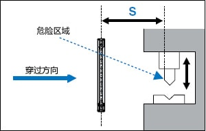
human body detection
S = K × T + C 40 < d ≦ 70
K = 1600 mm/s (approach speed [assumes human walking speed])
T = maximum time required for machine to stop + grating response time
C = 850 mm (crossing distance [a value corresponding to the standard length of a human arm])
Detection of hands and fingers
S=K × T + 8(d - 14) d ≦ 40
K = 2000 mm/s (approach velocity [assumes the passing velocity of the hand])
T = maximum time required for machine to stop + grating response time
d = grating detection capability
Note: If S is greater than or equal to 500 mm, perform the calculation again with a value of K equal to 1600. If the calculated S value again is less than or equal to 500 mm, set the S value to 500 mm.
The relationship between the maximum time it takes for the machine to stop and the safety distance
The T value in the formula consists of the following two parameters.
T = maximum time required for machine to stop + grating response time (ON ? OFF)
When K (passing speed) = 2000 mm/s For example, when using the GL-R08H grating (which has a response time of 0.0069 s)
S = 2000 mm/s × (the maximum time it takes for the machine to stop + 0.0069 s) + C
Multiply the maximum time it takes for the machine to stop by the traversing speed (2000 mm/s) as shown above, so even if the maximum time it takes for the machine to stop increases by only 1 second, the safety distance increases (2000 mm /s × 1 s = 2000 mm). For every 1 ms increase in light grid response time, the safety distance increases by 2 mm.
Protective areas must be configured to ensure a safe distance. The safety distance should be calculated according to the laws, regulations and standards of the country or region where the laser scanner SZ is installed and used and the specifications given in this document.
Laser scanner installation and safety distance
Example of area guarding (approaching direction parallel to guarded area)

S = K × T + C + A (according to ISO 13855 and IEC 61496-3 standards)
· S: Safety distance (mm)
K: Approach velocity of the body or body part (mm/s)
T: total response time (t1 + t2; s)
t1: SZ response time (s)
t2: The maximum time required for the machine to stop after receiving the OSSD signal from SZ (s)
· C: Distance (mm) of the body part approaching the hazardous area before passing through the SZ protective area 1200 - 0.4 × H (850 mm or more)
1200 - 0.4 × H (850 mm or higher) 47.24" - 0.4 × H (33.46" or higher)
· H: The height (mm) of the detection plane relative to the floor or other reference surface. 1000 ≥ H ≥ 15 × (d - 50)
d: SZ minimum detectable object size (mm)
· A: Additional distance of SZ protective area (mm)
P1, P2, P3: The protection distance configured as the SZ protection zone
W1, W2: Hazardous area width
B: Distance between the edge of the danger zone and the start of the detection zone on SZ
D: Unprotected space
Danger
· When the SZ is installed, the unprotected space (D) between the guarded area and the guarded structure must be smaller than the minimum size of the detectable object. This requirement is to prevent the machine operator from approaching the hazardous area through this space (D). If the smallest detectable object cannot be detected by the SZ due to the presence of space (D) between the protective field and the protective structure, additional protective measures must be taken.
· If the height "H" of the inspection plane (protective area) is greater than 300 mm (200 mm for non-industrial applications), there is a risk of inadvertently missing inspections by entering from below the inspection plane (protective area). This factor must be taken into account when conducting a risk assessment prior to installation of the SZ, and additional measures should be taken if necessary.
· If you have selected a minimum detectable object size of 150 mm, and the "H" value (height of the detection plane) exceeds 1000 mm. In this case, if you want to use SZ as an area guard (approach direction parallel to the guard area), you must choose a minimum detectable object size of 70 mm or less.
Example of Safe Distance Calculation
K = 1600 mm/s, the approach velocity of the body or body part (constant)
· T = t1 + t2 = 0.59, total response time
t1 = 0.09 s, SZ response time (variable)
t2 = 0.5 s, the maximum time required for the machine to stop after receiving the OSSD signal from SZ
· C = 1200 - 0.4 × H = 1080 mm
· H = 300 mm 11.81", the height of the inspection plane measured from the floor. This value must satisfy the following inequality: H ≥ 15 × (d - 50) H ≥ 15 × (d - 1.97").
d = 70 mm minimum detectable object size (variable)
A = 100 mm SZ additional distance for the protective field
B = 59 mm distance between the edge of the danger zone and the start of the detection zone on the SZ
· W1 = W2 = 1000 mm, hazardous area width
safe distance
S = K × T + C + A
= 1600 × 0.59 + 1080 + 100 = 2124 mm
Guard distance configured as SZ guard zone
P1 = S - B = 2065mm
P2 = S + W1 = 3124mm
P3 = S + W2 = 3124mm
When setting the above protection area, if there is a high reflectivity background within 1.5 m from the boundary of the protection area, an additional distance of 200 mm must be added as an additional safety distance for P1, P2 and P3. We recommend that you mark the floor to indicate designated protected areas.